Machinists make the parts every other trade depends on, to sizes measured in thousandths of an inch. Here are a few of the people who made that kind of accuracy possible.
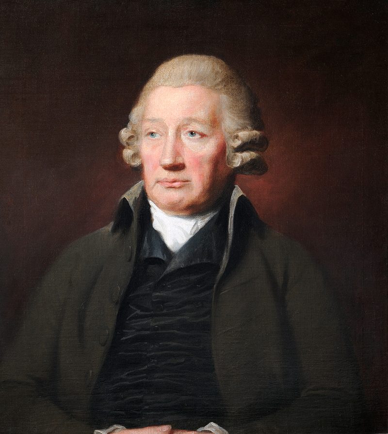
Portrait of John Wilkinson by Lemuel Francis AbbottLemuel Francis Abbott (1760 to 1802), about 1790s. Public domain. Wikimedia Commons. Image source
John Wilkinson bores a true cylinder
1774 to 1776 · John Wilkinson (1728 to 1808) and James Watt (1736 to 1819)
In the 1770s James Watt had a better steam engine on paper, but he had a problem in the shop. Nobody could make a big iron cylinder round and straight enough. Steam leaked past the piston and the engine wasted its power.
John Wilkinson was an ironmaster with works at Bersham in Wales and in Shropshire. In January 1774 he patented a new way of boring cannon from solid castings. The casting turned while the cutting tool was held steady.
He used the same thinking on engine cylinders. In his boring mill the bar that carried the cutter ran right through the cylinder and was supported at both ends, so it could not sag or wander. The bore came out true along its whole length.
From 1775 Wilkinson's works bored the cylinders for Boulton and Watt's early engines. With a piston that fit, Watt's engine finally worked as he had planned.
Historians often call Wilkinson's boring mill one of the first real machine tools. The idea of a rigid tool, well supported, cutting to a true line is still the first rule of good machining.
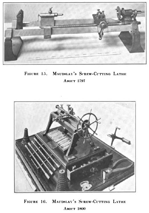
Maudslay's screw-cutting lathes of about 1797 and 1800, from English and American Tool Builders (1916)Joseph Wickham Roe (book), photographer unknown, 1916. Public domain. Wikimedia Commons. Image source
Henry Maudslay's screw-cutting lathe
1797 to about 1800 · Henry Maudslay (1771 to 1831)
Before 1800, most screws were cut by hand, and no two were quite the same. A nut from one bolt seldom fit another.
Henry Maudslay was born in Woolwich, near London, in 1771. As a young man he worked for the inventor Joseph Bramah and became his foreman. He then set up his own workshop in London in the late 1790s.
Around 1800 Maudslay built a screw-cutting lathe made almost entirely of metal. A slide rest held the cutting tool firmly, instead of in the turner's hands. A leadscrew, geared to the spindle, moved the tool along at a steady rate, so the lathe could cut an accurate thread again and again. A dial let him set the depth of cut. That lathe is still kept at the Science Museum in London.
Maudslay cared about flat surfaces and exact measurement, and he passed that on. Young engineers who worked in his shop included Joseph Whitworth and James Nasmyth, who went on to build famous machine tools of their own.
Every engine lathe with a leadscrew and carriage carries a little of Maudslay's design.
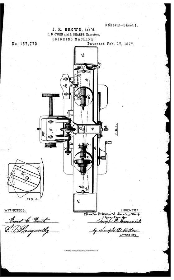
Drawing from Joseph R. Brown's US patent 187,770 for a grinding machine, 27 February 1877Joseph R. Brown (patent drawing), 1877. Public domain (US patent drawing). United States Patent and Trademark Office via Google Patents. Image source
Joseph Brown measures in thousandths
1851 to 1877 · Joseph R. Brown (1810 to 1876) and Lucian Sharpe (1830 to 1899)
Joseph Rogers Brown trained as a machinist and ran a clock and tool business in Providence, Rhode Island. In 1853 he took Lucian Sharpe into partnership. Their firm became Brown and Sharpe.
In 1851 Brown developed a vernier caliper that could read to a thousandth of an inch. It put a level of accuracy that used to need a lab into a machinist's pocket.
In 1867 Brown and Sharpe visited the Paris Exposition and saw the Palmer system, a French screw gauge patented in 1848. Back home, they used the same idea of a fine screw and a marked thimble to build a pocket sheet metal gauge. They added ways to take up wear in the screw and anvils. It is often called the first practical micrometer.
Brown kept going. He built a universal milling machine in 1862, and in 1877 he patented a grinding machine with a swivelling table that could grind straight work and tapers, the drawing shown here.
Next time you read a mic or a vernier, you are using ideas Brown and Sharpe made common.
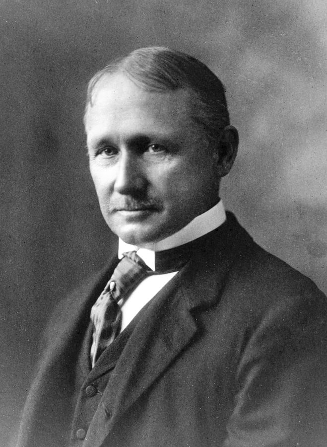
Frederick Winslow Taylor, about 1907Gessford studio, New York, about 1907. Public domain. Stevens Institute of Technology Taylor Collection via Wikimedia Commons. Image source
Taylor and White make tools that glow
1898 to 1900 · Frederick W. Taylor (1856 to 1915) and Maunsel White (1856 to 1912)
Around 1898, carbon and early alloy tool steels went soft when they got hot. Push the cutting speed too far and the tool lost its edge in minutes. Shops cut most metals at about 10 to 40 feet per minute.
At the Bethlehem Steel works in Pennsylvania, engineer Frederick W. Taylor and metallurgist Maunsel White ran careful tests on tool steels containing chromium and tungsten. They kept careful records and tried heating the tools far hotter than most steelmakers thought was safe.
The result surprised everyone. Treated this way, a tool held its edge even when it ran at a dull red heat. At the Paris Exposition of 1900 they showed a lathe peeling soft steel at about 60 to 180 feet per minute, with chips coming off so hot they turned blue.
Taylor and White patented the process in 1901, and the Franklin Institute gave them its Elliott Cresson Medal in 1902. Shops soon needed heavier, stiffer machines to keep up with the new tools.
Today's high-speed steel bits grew straight out of their work.
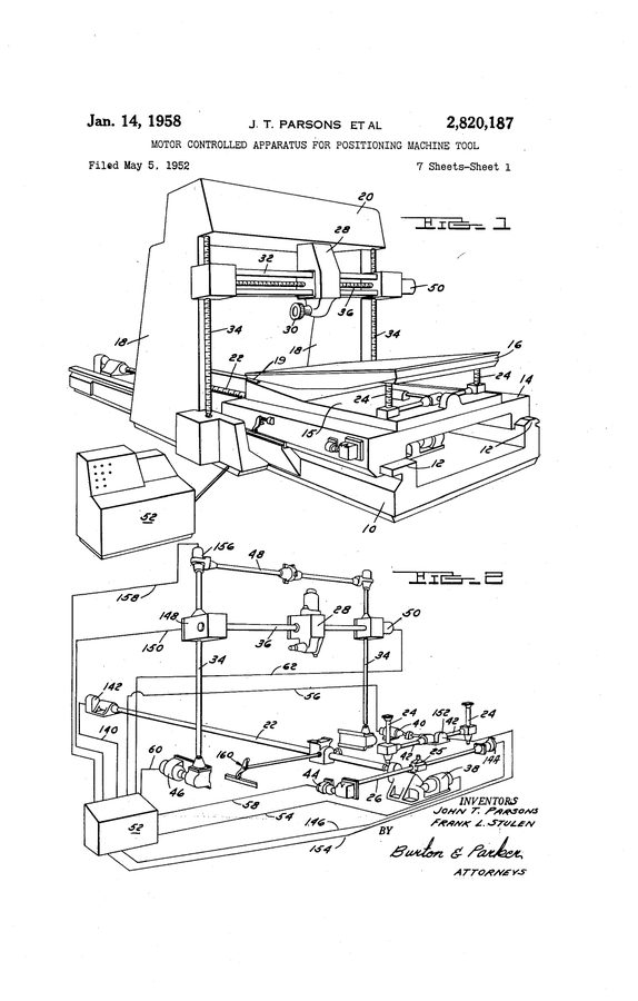
Drawing from US patent 2,820,187 by J. T. Parsons and F. L. Stulen, granted 14 January 1958John T. Parsons and Frank L. Stulen (patent drawing), 1958. Public domain (US patent drawing). United States Patent and Trademark Office via Google Patents. Image source
John Parsons teaches a machine to read numbers
1947 to 1958 · John T. Parsons (1913 to 2007) and Frank L. Stulen
In the late 1940s John T. Parsons ran a company in Michigan that made helicopter rotor blades. Each blade needed accurate templates, and laying them out by hand was slow.
Parsons and his engineer Frank L. Stulen used an IBM punched-card machine to calculate points along the blade's curve. A machinist then moved a machine to each set of numbers, one point after another. Parsons wondered: why not let the numbers drive the machine directly?
In 1949 the US Air Force gave Parsons a contract to develop the idea. The Servomechanisms Laboratory at the Massachusetts Institute of Technology (MIT) joined the project and built the motor controls. In 1952 MIT showed a milling machine that moved its three axes on its own, following instructions punched into paper tape.
Parsons and Stulen filed their patent in 1952, and it was granted in 1958. Parsons received the National Medal of Technology in 1985 and joined the National Inventors Hall of Fame in 1993.
Every CNC mill and lathe running a program today follows the path they started.